Robot 6-Axis/es: Difference between revisions
Emagdalena (talk | contribs) (Created page with "Segmento") |
(Updating to match new version of source page) |
||
| (44 intermediate revisions by 4 users not shown) | |||
| Line 1: | Line 1: | ||
| ⚫ | |||
Este artículo trata sobre incluir en FreeCAD para su simulación un robot industrial estándar de 6 ejes |
|||
{{TutorialInfo/es |
|||
|Topic= Ambiente de trabajo Robot |
|||
|Level= Intermedio |
|||
|Time= Desconocido |
|||
|Author= |
|||
|FCVersion= |
|||
|Files= |
|||
}} |
|||
==Vista general== |
|||
<div class="mw-translate-fuzzy"> |
|||
Este artículo trata de llevar un robot industrial estándar de 6 ejes a FreeCAD para su simulación en el [[Image:Workbench_Robot.svg|24px]] [[Robot Workbench/es|Ambiente de trabajo Robot]] |
|||
</div> |
|||
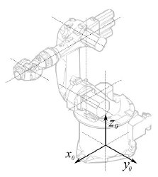
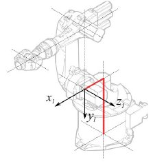
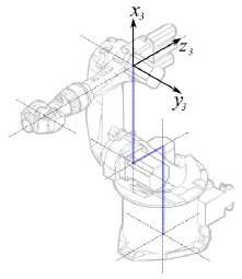
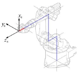
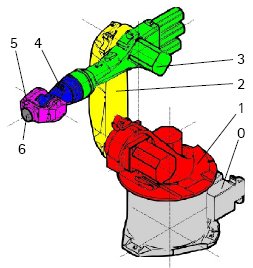
La siguiente descripción sigue el sistema de [http://en.wikipedia.org/wiki/Denavit-Hartenberg_Parameters parámetros Denavit-Hartenberg], como también se describe en el libro de John J. Craigs "Introducción a la robótica". |
La siguiente descripción sigue el sistema de [http://en.wikipedia.org/wiki/Denavit-Hartenberg_Parameters parámetros Denavit-Hartenberg], como también se describe en el libro de John J. Craigs "Introducción a la robótica". |
||
== Ejemplo Kuka == |
== Ejemplo Kuka == |
||
| Line 20: | Line 35: | ||
|- |
|- |
||
! Segmento |
! Segmento |
||
! Parámetro |
|||
! Parameter |
|||
! Descripción |
|||
! Description |
|||
|- |
|- |
||
| [[Image:KukaBase.jpg]] |
| [[Image:KukaBase.jpg]] |
||
|| |
|| |
||
|| Base |
|| Base de configuración |
||
|- |
|- |
||
| [[Image:KukaSegment1.jpg]] |
| [[Image:KukaSegment1.jpg]] |
||
| Line 37: | Line 52: | ||
<math>\alpha_{1} = −90</math>° |
<math>\alpha_{1} = −90</math>° |
||
|| |
|| Segmento 1 |
||
|- |
|- |
||
| [[Image:KukaSegment2.jpg]] |
| [[Image:KukaSegment2.jpg]] |
||
| Line 50: | Line 65: | ||
<math>\alpha_{2} = 0</math>° |
<math>\alpha_{2} = 0</math>° |
||
|| |
|| Segmento 2 |
||
|- |
|- |
||
| [[Image:KukaSegment3.jpg]] |
| [[Image:KukaSegment3.jpg]] |
||
| Line 63: | Line 78: | ||
<math>\alpha_{3} = 90</math>° |
<math>\alpha_{3} = 90</math>° |
||
|| |
|| Segmento 3 |
||
|- |
|- |
||
| [[Image:KukaSegment4.jpg]] |
| [[Image:KukaSegment4.jpg]] |
||
| Line 76: | Line 91: | ||
<math>\alpha_{4} = -90</math>° |
<math>\alpha_{4} = -90</math>° |
||
|| |
|| Segmento 4 |
||
|- |
|- |
||
| [[Image:KukaSegment5.jpg]] |
| [[Image:KukaSegment5.jpg]] |
||
| Line 89: | Line 104: | ||
<math>\alpha_{5} = 90</math>° |
<math>\alpha_{5} = 90</math>° |
||
|| |
|| Segmento 5 |
||
|- |
|- |
||
| [[Image:KukaSegment6.jpg]] |
| [[Image:KukaSegment6.jpg]] |
||
| Line 102: | Line 117: | ||
<math>\alpha_{6} = 180</math>° |
<math>\alpha_{6} = 180</math>° |
||
|| |
|| Segmento 6 |
||
|} |
|} |
||
Esto conduce a la tabla siguiente: |
|||
This leads to following table: |
|||
{| class="wikitable" style="color:green; background-color:#ffffcc;" cellpadding="5" cellspacing="0" border="1" |
{| class="wikitable" style="color:green; background-color:#ffffcc;" cellpadding="5" cellspacing="0" border="1" |
||
|+ <div class="mw-translate-fuzzy"> |
|||
|+ '''Kinematik table''' |
|||
'''Tabla cinemática''' |
|||
</div> |
|||
|- |
|- |
||
! <math>i</math> !! <math>\theta</math> !! <math>d</math> !! <math>a</math> !! <math>\alpha</math> |
! <math>i</math> !! <math>\theta</math> !! <math>d</math> !! <math>a</math> !! <math>\alpha</math> |
||
| Line 125: | Line 142: | ||
|} |
|} |
||
Ya que los robots Kuka no tienen todos los ejes a 0 en la posición dibujada en L, tenemos que cambiar el eje 2 y 3 por 90°. |
|||
Since the Kuka robots do not have all axis to 0 in the drawn L-Position, we have to change |
|||
axis 2 & 3 by 90°. |
|||
{| class="wikitable" style="color:green; background-color:#ffffcc;" cellpadding="5" cellspacing="0" border="1" |
{| class="wikitable" style="color:green; background-color:#ffffcc;" cellpadding="5" cellspacing="0" border="1" |
||
|+ <div class="mw-translate-fuzzy"> |
|||
|+ '''Kinematik table''' |
|||
'''Tabla cinemática''' |
|||
</div> |
|||
|- |
|- |
||
! <math>i</math> !! <math>\theta</math> !! <math>d</math> !! <math>a</math> !! <math>\alpha</math> |
! <math>i</math> !! <math>\theta</math> !! <math>d</math> !! <math>a</math> !! <math>\alpha</math> |
||
| Line 147: | Line 165: | ||
|} |
|} |
||
En la hoja de datos encontramos información adicional sobre los ejes: |
|||
In the data sheet we find additional information about the axis: |
|||
[[Image:KukaAxisData.jpg]] |
[[Image:KukaAxisData.jpg]] |
||
Lo que conduce a esta tabla completa: |
|||
That leads to this complete table: |
|||
{| class="wikitable" style="color:green; background-color:#ffffcc;" cellpadding="5" cellspacing="0" border="1" |
{| class="wikitable" style="color:green; background-color:#ffffcc;" cellpadding="5" cellspacing="0" border="1" |
||
|+ <div class="mw-translate-fuzzy"> |
|||
|+ '''Kinematik table''' |
|||
'''Tabla cinemática''' |
|||
</div> |
|||
|- |
|- |
||
! <math>i</math> !! <math>\theta</math> !! <math>d</math> !! <math>a</math> !! <math>\alpha</math> !! <math>\theta_{min}</math> !! <math>\theta_{max}</math> !! Axis Speed |
! <math>i</math> !! <math>\theta</math> !! <math>d</math> !! <math>a</math> !! <math>\alpha</math> !! <math>\theta_{min}</math> !! <math>\theta_{max}</math> !! Axis Speed |
||
| Line 169: | Line 190: | ||
|} |
|} |
||
=== |
=== Representación visual === |
||
FreeCAD puede generar una basta representación visual de la tabla cinemática. Pero si quieres acercarte más a la realidad puedes utilizar un archivo VRML con la forma del robot para la simulación. Por ejemplo, [http://kuka.com Kuka] proporciona archivos VRML de sus modelos. El archivo VRML es cargado con la especificación del robot en FreeCAD. Para permitir a FreeCAD mover los ejes tenemos que editar el archivo VRML e insertar nodos de transformación especiales que FreeCAD pueda encontrar y manipular. |
|||
FreeCAD can generate a rough visual out of the kinematic table. But if you want closer to reality you can use a VRML file with the robot shape for the simulation. |
|||
E.g. [http://kuka.com Kuka] delivers for its model VRML files. |
|||
The VRML file gets loaded while the creation of the specific robot in FreeCAD. In order to allow FreeCAD to move the axis we have to edit the VRML file and insert special transformation nodes FreeCAD can find and manipulate. |
|||
Otra vez mostrado por el ejemplo Kuka KR 16. Empezando desde la línea 1: |
|||
Beginning from line 1: |
|||
#VRML V2.0 utf8 |
#VRML V2.0 utf8 |
||
| Line 201: | Line 219: | ||
[ |
[ |
||
... |
... |
||
Verás que este archivo es exportado con un software de simulación de robots llamado Tecnomatix. Elimina ese aviso y añade la URL de donde has obtenido el archivo, porque Tecnomatix no tiene ningún copyright en el contenido del archivo. Es solo un conversor! Antes de nada eliminamos el nodo de Background. Luego eliminamos el nodo de rotación y escala para tener el modelo en mm y Z a la derecha. |
|||
Justo al final: |
|||
Right at the end: |
|||
] } |
] } |
||
] } |
] } |
||
| Line 221: | Line 239: | ||
#} |
#} |
||
Desmarcar como comentario el sensor de tiempo TimeSensor y las 6 rutas. Estas 6 líneas te dan una pista de la situación del eje real del robot! Primero busca por "AXIS_04_OBJ" que te lleva a esta parte: |
|||
... |
... |
||
Transform { rotation 1 0 0 1.570796 children [ |
Transform { rotation 1 0 0 1.570796 children [ |
||
| Line 244: | Line 262: | ||
[ |
[ |
||
... |
... |
||
Tienes que insertar justo encima de la definición de este nodo la línea '''"DEF FREECAD_AXIS1 Transform { rotation 0 1 0 0 children ["''' la cual es el anclaje para que FreeCAD pueda mover el eje. |
|||
Ahora haz lo mismo para '''FREECAD_AXIS2''','''FREECAD_AXIS3''','''FREECAD_AXIS4''','''FREECAD_AXIS5''' y '''FREECAD_AXIS6'''. No olvides cerrar los corchetes al final del archivo y listo! |
|||
Don't forget the closing brackets at the end of the file and you're done! |
|||
Puedes cargar el VRML para instalar el robot: |
|||
App.activeDocument().addObject("Robot::RobotObject","Robot") |
App.activeDocument().addObject("Robot::RobotObject","Robot") |
||
App.activeDocument().Robot.RobotVrmlFile = "C:/_Projekte/FreeCAD0.9_build/mod/Robot/Lib/Kuka/kr16.wrl" |
App.activeDocument().Robot.RobotVrmlFile = "C:/_Projekte/FreeCAD0.9_build/mod/Robot/Lib/Kuka/kr16.wrl" |
||
Lo cual debería dar este resultado: |
|||
which should give you that result: |
|||
[[Image:KukaKR16FreeCAD.jpg]] |
[[Image:KukaKR16FreeCAD.jpg]] |
||
| Line 260: | Line 277: | ||
{| class="wikitable" style="color:green; background-color:#ffffcc;" cellpadding="5" cellspacing="0" border="1" |
{| class="wikitable" style="color:green; background-color:#ffffcc;" cellpadding="5" cellspacing="0" border="1" |
||
|+ <div class="mw-translate-fuzzy"> |
|||
|+ '''Kinematik table''' |
|||
'''Tabla cinemática''' |
|||
</div> |
|||
|- |
|- |
||
! <math>i</math> !! <math>\theta</math> !! <math>d</math> !! <math>a</math> !! <math>\alpha</math> !! <math>\theta_{min}</math> !! <math>\theta_{max}</math> !! Axis Speed |
! <math>i</math> !! <math>\theta</math> !! <math>d</math> !! <math>a</math> !! <math>\alpha</math> !! <math>\theta_{min}</math> !! <math>\theta_{max}</math> !! Axis Speed |
||
| Line 283: | Line 302: | ||
{| class="wikitable" style="color:green; background-color:#ffffcc;" cellpadding="5" cellspacing="0" border="1" |
{| class="wikitable" style="color:green; background-color:#ffffcc;" cellpadding="5" cellspacing="0" border="1" |
||
|+ <div class="mw-translate-fuzzy"> |
|||
|+ '''Kinematik table''' |
|||
'''Tabla cinemática''' |
|||
</div> |
|||
|- |
|- |
||
! <math>i</math> !! <math>\theta</math> !! <math>d</math> !! <math>a</math> !! <math>\alpha</math> !! <math>\theta_{min}</math> !! <math>\theta_{max}</math> !! Axis Speed |
! <math>i</math> !! <math>\theta</math> !! <math>d</math> !! <math>a</math> !! <math>\alpha</math> !! <math>\theta_{min}</math> !! <math>\theta_{max}</math> !! Axis Speed |
||
| Line 300: | Line 321: | ||
|} |
|} |
||
=== Links === |
|||
[[Category:User Documentation]] |
|||
| ⚫ | |||
* [https://link.springer.com/referenceworkentry/10.1007%2F978-3-540-30301-5_2 Springer Handbook of Robotics, section Kinematics, p 9-33]. |
|||
* [https://www.youtube.com/watch?v=qZB3_gKBwf8 Denavit-Hartenberg Parameter 3D Video Tutorial] Denavit-Hartenberg Parameter 3D Video Tutorial for a KUKA industry robot on YouTube (german). |
|||
* [https://www.youtube.com/watch?v=rA9tm0gTln8 Denavit-Hartenberg Reference Frame Layout] Denavit-Hartenberg Reference Frame Layout on YouTube. |
|||
* [http://www.roboanalyzer.com/ RoboAnalyzer] RoboAnalyzer is a 3D model based software that can be used to teach and learn the Robotics concepts. |
|||
{{Tutorials navi{{#translation:}}}} |
|||
{{Robot_Tools_navi{{#translation:}}}} |
|||
{{Userdocnavi{{#translation:}}}} |
|||
Revision as of 21:24, 13 August 2021
| Tema |
|---|
| Ambiente de trabajo Robot |
| Nivel |
| Intermedio |
| Tiempo para completar |
| Desconocido |
| Autores |
| Versión de FreeCAD |
| Archivos de ejemplos |
| Ver también |
| None |
Vista general
Este artículo trata de llevar un robot industrial estándar de 6 ejes a FreeCAD para su simulación en el Ambiente de trabajo Robot
La siguiente descripción sigue el sistema de parámetros Denavit-Hartenberg, como también se describe en el libro de John J. Craigs "Introducción a la robótica".
Ejemplo Kuka

|
|

|
Cinemática
Esto conduce a la tabla siguiente:
| 1 | q1 | 675 mm | 260 mm | -90° |
| 2 | q2 - 90° | 0 mm | 680 mm | 0° |
| 3 | q3 | 0 mm | 0 mm | 90° |
| 4 | q4 | -670 mm | 0 mm | -90° |
| 5 | q5 | 0 mm | 0 mm | 90° |
| 6 | q6 | -158 mm | 0 mm | 180° |
Ya que los robots Kuka no tienen todos los ejes a 0 en la posición dibujada en L, tenemos que cambiar el eje 2 y 3 por 90°.
| 1 | q1 | 675 mm | 260 mm | -90° |
| 2 | q2 | 0 mm | 680 mm | 0° |
| 3 | q3 - 90° | 0 mm | 0 mm | 90° |
| 4 | q4 | -670 mm | 0 mm | -90° |
| 5 | q5 | 0 mm | 0 mm | 90° |
| 6 | q6 | -158 mm | 0 mm | 180° |
En la hoja de datos encontramos información adicional sobre los ejes:
Lo que conduce a esta tabla completa:
| Axis Speed | |||||||
|---|---|---|---|---|---|---|---|
| 1 | 0 | 675 | 260 | -90 | -185 | 185 | 156 |
| 2 | 0 | 0 | 680 | 0 | -155 | 35 | 156 |
| 3 | - 90 | 0 | 0 | 90 | -130 | 154 | 156 |
| 4 | 0 | -670 | 0 | -90 | -350 | 350 | 330 |
| 5 | 0 | 0 | 0 | 90 | -130 | 130 | 330 |
| 6 | 0 | -158 | 0 | 180 | -350 | 350 | 615 |
Representación visual
FreeCAD puede generar una basta representación visual de la tabla cinemática. Pero si quieres acercarte más a la realidad puedes utilizar un archivo VRML con la forma del robot para la simulación. Por ejemplo, Kuka proporciona archivos VRML de sus modelos. El archivo VRML es cargado con la especificación del robot en FreeCAD. Para permitir a FreeCAD mover los ejes tenemos que editar el archivo VRML e insertar nodos de transformación especiales que FreeCAD pueda encontrar y manipular.
Otra vez mostrado por el ejemplo Kuka KR 16. Empezando desde la línea 1:
#VRML V2.0 utf8
#
# This VRML97 file was exported using eM-Workplace
# (c) Tecnomatix Technologies GmbH & Co. KG
#     Heisenberg-Bogen 1
#     D-85609 Aschheim-Dornach
#     GERMANY
#
#Background
#{
#   skyColor   [0.752941 0.752941 0.752941]
#}
Transform
{
   #rotation 1 0 0 -1.5707963
   #scale .001 .001 .001
   children
   [
           DEF AOBJ_0001_000_TRAFO Transform
           {
              children
              [
...
Verás que este archivo es exportado con un software de simulación de robots llamado Tecnomatix. Elimina ese aviso y añade la URL de donde has obtenido el archivo, porque Tecnomatix no tiene ningún copyright en el contenido del archivo. Es solo un conversor! Antes de nada eliminamos el nodo de Background. Luego eliminamos el nodo de rotación y escala para tener el modelo en mm y Z a la derecha.
Justo al final:
  ] }
  ] }
  ] }
  ]
}
#ROUTE SENS_04_OBJ.rotation_changed TO AXIS_04_OBJ.rotation
#ROUTE SENS_27_OBJ.rotation_changed TO AXIS_27_OBJ.rotation
#ROUTE SENS_32_OBJ.rotation_changed TO AXIS_32_OBJ.rotation
#ROUTE SENS_44_OBJ.rotation_changed TO AXIS_44_OBJ.rotation
#ROUTE SENS_46_OBJ.rotation_changed TO AXIS_46_OBJ.rotation
#ROUTE SENS_49_OBJ.rotation_changed TO AXIS_49_OBJ.rotation
#DEF AnySIMTimer TimeSensor
#{
#   cycleInterval 1.000000
#   loop          TRUE
#}
Desmarcar como comentario el sensor de tiempo TimeSensor y las 6 rutas. Estas 6 líneas te dan una pista de la situación del eje real del robot! Primero busca por "AXIS_04_OBJ" que te lleva a esta parte:
...
    Transform { rotation 1 0 0 1.570796 children [
        DEF SENS_04_OBJ-0001 CylinderSensor
        {
           diskAngle 1.570796
           minAngle  -3.228859
           maxAngle  3.228859
           offset    0.000000
        }
      DEF FREECAD_AXIS1 Transform { rotation 0 1 0 0 children [
      DEF AXIS_04_OBJ-0001 Transform
     {
        children
        [
        Transform { rotation 1 0 0 -1.570796 children [
           DEF AOBJ_0001_003_TRAFO Transform
           {
              rotation 1.000000 0.000000 0.000000 3.141593
              translation -600.000000 500.000000 300.000000
              children
              [
...
Tienes que insertar justo encima de la definición de este nodo la línea "DEF FREECAD_AXIS1 Transform { rotation 0 1 0 0 children [" la cual es el anclaje para que FreeCAD pueda mover el eje.
Ahora haz lo mismo para FREECAD_AXIS2,FREECAD_AXIS3,FREECAD_AXIS4,FREECAD_AXIS5 y FREECAD_AXIS6. No olvides cerrar los corchetes al final del archivo y listo!
Puedes cargar el VRML para instalar el robot:
App.activeDocument().addObject("Robot::RobotObject","Robot")
App.activeDocument().Robot.RobotVrmlFile = "C:/_Projekte/FreeCAD0.9_build/mod/Robot/Lib/Kuka/kr16.wrl"
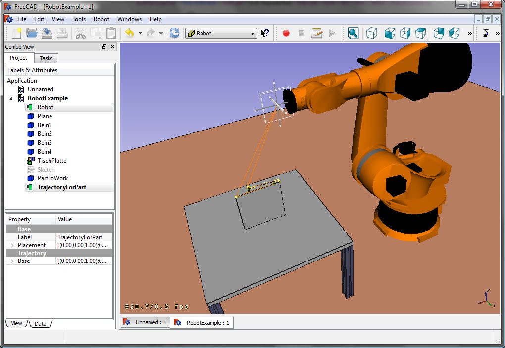
Lo cual debería dar este resultado:
KR 210
| Axis Speed | |||||||
|---|---|---|---|---|---|---|---|
| 1 | 0 | 750 | 350 | -90 | -185 | 185 | 156 |
| 2 | 0 | 0 | 1250 | 0 | -155 | 35 | 156 |
| 3 | - 90 | 0 | 0 | 90 | -130 | 154 | 156 |
| 4 | 0 | -1100 | 0 | -90 | -350 | 350 | 330 |
| 5 | 0 | 0 | 0 | 90 | -130 | 130 | 330 |
| 6 | 0 | -230 | 0 | 180 | -350 | 350 | 615 |
KR 500
| Axis Speed | |||||||
|---|---|---|---|---|---|---|---|
| 1 | 0 | 1045 | 500 | -90 | -185 | 185 | 156 |
| 2 | 0 | 0 | 1300 | 0 | -155 | 35 | 156 |
| 3 | - 90 | 0 | 0 | 90 | -130 | 154 | 156 |
| 4 | 0 | -1025 | 0 | -90 | -350 | 350 | 330 |
| 5 | 0 | 0 | 0 | 90 | -130 | 130 | 330 |
| 6 | 0 | -250 | 0 | 180 | -350 | 350 | 615 |
Links
- Springer Handbook of Robotics, section Kinematics, p 9-33.
- Denavit-Hartenberg Parameter 3D Video Tutorial Denavit-Hartenberg Parameter 3D Video Tutorial for a KUKA industry robot on YouTube (german).
- Denavit-Hartenberg Reference Frame Layout Denavit-Hartenberg Reference Frame Layout on YouTube.
- RoboAnalyzer RoboAnalyzer is a 3D model based software that can be used to teach and learn the Robotics concepts.
- Trajectories, non parametric: Create a trajectory, Set default orientation, Set default values, Insert waypoint, Insert waypoint (mouse)
- Trajectories, parametric: Create a trajectory from edges, Dress-up trajectory, Trajectory compound
- Getting started
- Installation: Download, Windows, Linux, Mac, Additional components, Docker, AppImage, Ubuntu Snap
- Basics: About FreeCAD, Interface, Mouse navigation, Selection methods, Object name, Preferences, Workbenches, Document structure, Properties, Help FreeCAD, Donate
- Help: Tutorials, Video tutorials
- Workbenches: Std Base, Arch, Assembly, CAM, Draft, FEM, Inspection, Mesh, OpenSCAD, Part, PartDesign, Points, Reverse Engineering, Robot, Sketcher, Spreadsheet, Start, Surface, TechDraw, Test Framework, Web
- Hubs: User hub, Power users hub, Developer hub
