Part Extrude
|
|
| Menu location |
|---|
| Part → Extrude |
| Workbenches |
| Part, Complete |
| Default shortcut |
| None |
| Introduced in version |
| - |
| See also |
| None |
Description
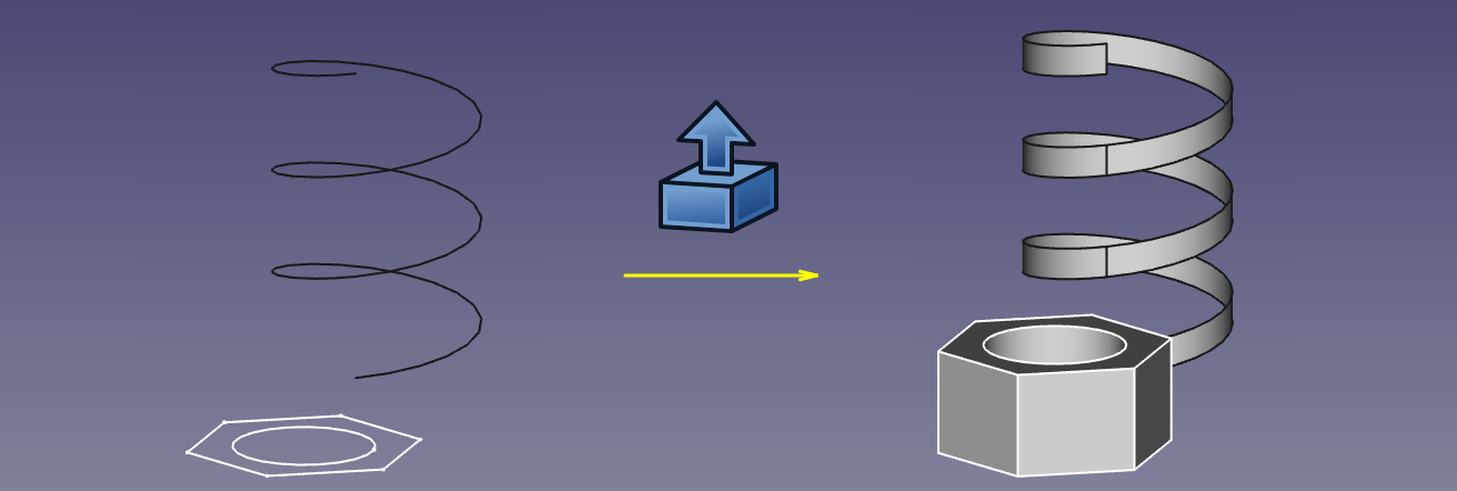
Part Extrude extends a shape by a specified distance, in a specified direction. The output shape type will vary depending on the input shape type and the options selected.
In most common scenarios, the following lists the expected output shape type from a given input shape type,
- Extrude a Vertex (point), will produce a lineal Edge (Line)
- Extrude a open edge (e.g. line, arc), will produce a open face (e.g. plane)
- Extrude a closed edge (e.g. circle), will optionally produce a closed face (e.g. an open ended cylinder) or if the parameter "solid" is "true" will produce a solid (e.g. a closed solid cylinder)
- Extrude a open Wire (e.g. a Draft Wire), will produce a open shell (several joined faces)
- Extrude a closed Wire (e.g. a Draft Wire), will optionally produce a shell (several joined faces) or if the parameter "solid" is "true" will produce a solid
- Extrude a face (e.g. plane), will produce a solid (e.g. Cuboid)
- Extrude a Draft Shape String, will produce a compound of solids (the string is a compound of the letters which are each a solid)
- Extrude a shell of faces, will produce a Compsolid.
How to use
- Select the shape(s) in the 3D view or in the Model tree
- Click on the
 Extrude icon in the toolbar, or go to the Part → Extrude menu
 - Set the direction and length and optionally other parameters (see the following Parameters section for more details).
- Click OK.
Alternatively, the selection can be done after launching the tool, by selecting one or more shape from the list in the Tasks panel.
The Model tree will list as many Extrude objects as there were selected shapes. Each input shape is placed underneath its Extrude object.
Parameters
The Extrude shape is defined by the following parameters, which can be edited after its creation in the Data tab.
- Base: the input shape (the shape upon which the Part Extrude was applied)
- Dir: the direction to extend the shape. If Dir Mode is 'Custom', you can edit Dir. Otherwise, Dir is read-only, and computed from the linked shape.
- Dir Link: parametric link to a edge (line) that sets the direction of extrusion. As of v0.17, this property is not supported by property editor.
- Dir Mode: sets how Dir is controlled. 'Custom' meand Dir is editable. 'Edge' means Dir is obtained from an edge (line) linked by Dir Link. 'Normal' means Dir is perpendicular to plane of the input shape.
- Length Fwd: The distance to extrude by. If both Length Fwd and Length Rev are zero, the length of Dir vector is used.
- Length Rev: Additional length to extrude against Dir.
- Solid: if True, extruding a closed edge or a closed wire will yeild a solid. If False, a shell will result.
- Reversed: reverses the extrusion to go against Dir.
- Symmetric: if True, extrusion is centered at the input shape, and total length is Length Fwd. Length Rev is ignored.
- Taper Angle and Taper Angle Rev: applies an angle to the extrusion, so that sides of the extrusion are drafted by the specified angle. Positive angle means the cross-section expands. Taper Angle Rev sets the taper for the reversed part of the extrusion (the part from Length Rev). As of v0.17, tapered extrusion is only supported for wires with no holes.
- Face Maker Class: sets C++ class name of face making code, which is used when making solids from wires. This property is here mainly for maintaining backward compatibility. Do not touch, unless you know what you are doing.
- Placement: the standard placement parameters
- Label: label to be shown in the Model tree (not available on Extrude creation)

